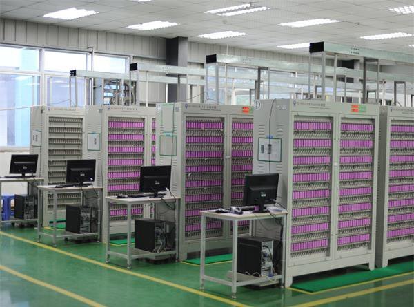
Commissioning a battery rack is not a single event; it is a sequence of verifications that ends with a signed record. In practice it runs in five phases: pre-energization inspection, BMS configuration and communications, protection trip testing, capacity and efficiency measurement, and thermal and site integration. Skipping the third phase is the most common mistake, and it is the one that produces nuisance trips and unexplained shutdowns during the first month of operation, when the site is under commercial pressure and every alarm is expensive.
This checklist is written for the commissioning engineer at a system integrator, working with rack-mounted lithium modules, a rack BMS or cluster controller, and a power conversion system (PCS) supplied by someone else. It covers what to verify, how to verify it, and what to record so that the handover pack survives an audit two years later.
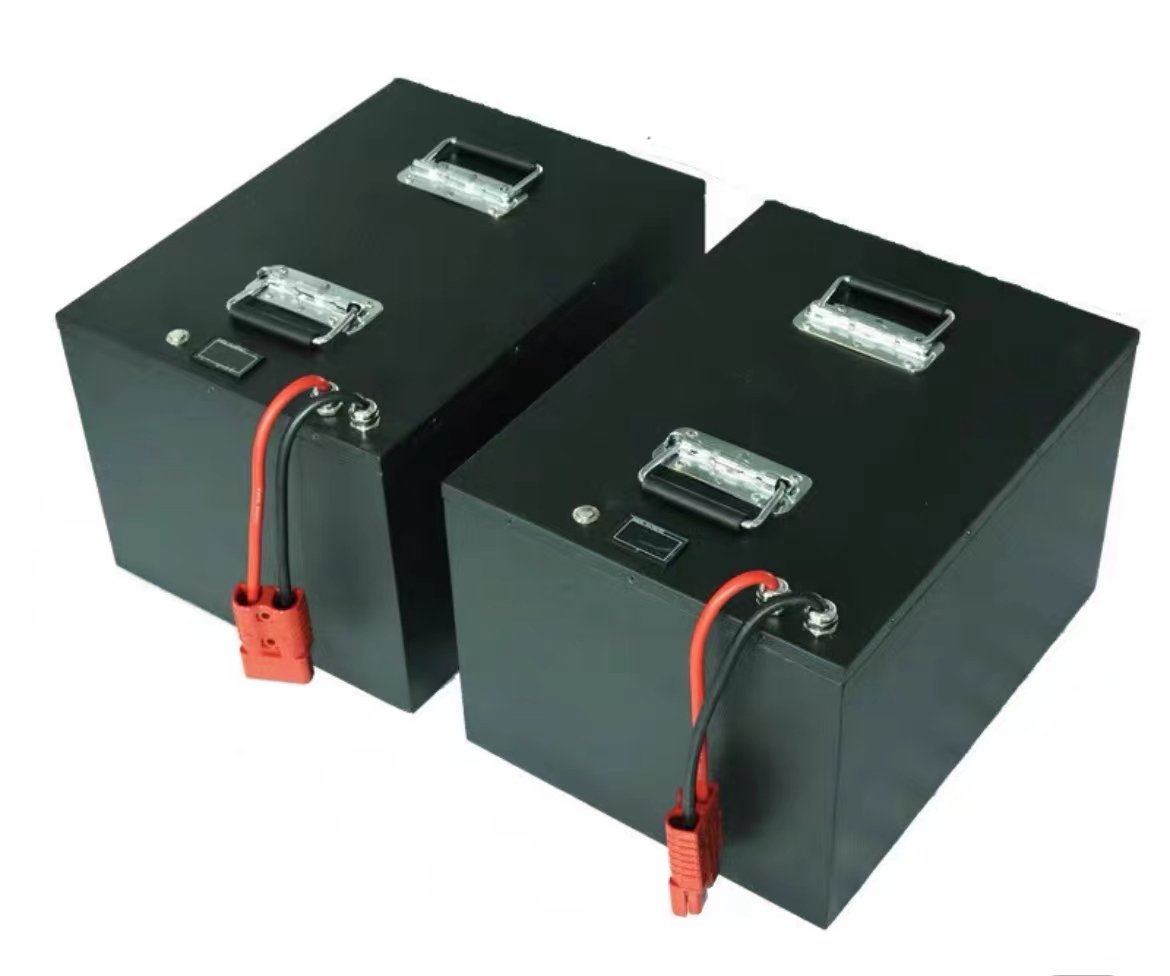
Define the commissioning boundary before the site visit
Most disputes about a “failed” commissioning come from an undefined boundary. Write down, before mobilisation, which of these the battery scope covers:
- Rack mechanical installation, module seating and inter-module busbar torque.
- Rack-to-PCS DC cabling, fusing and disconnect devices, or only the rack terminals.
- BMS addressing, cluster configuration and communication to the site controller or SCADA.
- Protection trip testing, including whether the PCS is required to respond.
- Capacity test at DC terminals, or round-trip efficiency measured at the AC meter.
- Fire detection interface, ventilation and environmental monitoring.
Items outside the battery scope still need an owner, because a capacity test cannot be completed if the PCS is not commissioned, and a protection test cannot be signed off if the site controller is not wired. Agreeing the boundary in writing converts a week of finger-pointing into an hour of planning.
Phase 1: pre-energization inspection
Everything in this phase happens with all contactors open and the DC disconnect locked off. The objective is to find installation defects before energy is applied, not after.
| Check | Method | Acceptance (typical) |
|---|---|---|
| Transport damage and module serials | Visual inspection; photograph each module label | No dents, swelling, electrolyte smell or cracked housing; serials logged against the delivery note |
| Resting cell voltages at receipt | BMS readout or module terminal measurement | Within the manufacturer’s shipping window; no module with an outlier cell |
| Module seating and retention | Physical check against the rack drawing | Fully seated, locking features engaged, no strain on busbars |
| Busbar and terminal torque | Calibrated torque wrench, marker applied after tightening | Manufacturer’s torque value; every fastener marked |
| Polarity and cabling | Continuity and polarity check before connection | Correct polarity at every terminal; no cross-phase or reverse connection |
| Insulation resistance | Insulation tester at the agreed test voltage, rack isolated from electronics where required | Above the manufacturer’s minimum; many integrators apply ≥ 1 MΩ at 500 V DC as a floor |
| Fuse and breaker ratings | Nameplate check against the single-line diagram | Rating and curve match the design; spares of the same rating on site |
| Grounding and bonding | Continuity measurement rack-to-earth | Bonding path continuous; resistance within the project’s earthing specification |
| Ventilation and clearance | Compare installed spacing with the layout | Clearances maintained; intake and exhaust unobstructed |
| Environmental conditions | Temperature and humidity log at rack height | Inside the operating envelope stated for the modules |
| Firmware and configuration baseline | Read BMS and controller versions | Recorded, and matching the released configuration for the project |
Two of these checks deserve emphasis. Cell voltage at receipt is the only chance to catch a module that was deep-discharged in transit or storage; a module sitting at a low state of charge for months may never recover its original capacity. Insulation resistance before first energization is much easier to investigate than after, when a fault can be confused with an inverter issue.
Phase 2: BMS configuration and communications
Before a rack is allowed to close its contactors, the BMS must know what it is connected to. Configuration errors here are common and they hide until the first protection event.
- Topology and addressing. Series count, parallel module count, and the address of each module or cluster. Dip switches or software addressing must match the drawing, and duplicates must be impossible.
- Protection settings. Cell overvoltage, cell undervoltage, pack overcurrent (charge and discharge), high and low temperature, and the recovery conditions for each. Record the values as configured, not as specified in a document.
- Current limits communicated to the PCS. Charge and discharge current limits, and how they derate at temperature extremes. If the PCS ignores these limits, the rack protection becomes the last line of defence rather than the first.
- State of charge and state of health reporting. Verify that SOC tracks a known partial charge and discharge, and that SOH is reported rather than left at a default.
- Communication integrity. CAN or RS-485 termination, baud rate, heartbeat interval and timeout behaviour. Pull one communication cable and confirm the system goes to a defined safe state rather than continuing to operate blind.
- Alarm mapping. Every BMS alarm should appear at the site controller with the correct severity. A rack that trips correctly but reports “communication fault” to the operator has a mapping problem, not a battery problem.
Record screenshots or exports of the configuration pages, with timestamps. When an alarm is investigated six months later, the configured thresholds at commissioning are the reference point.
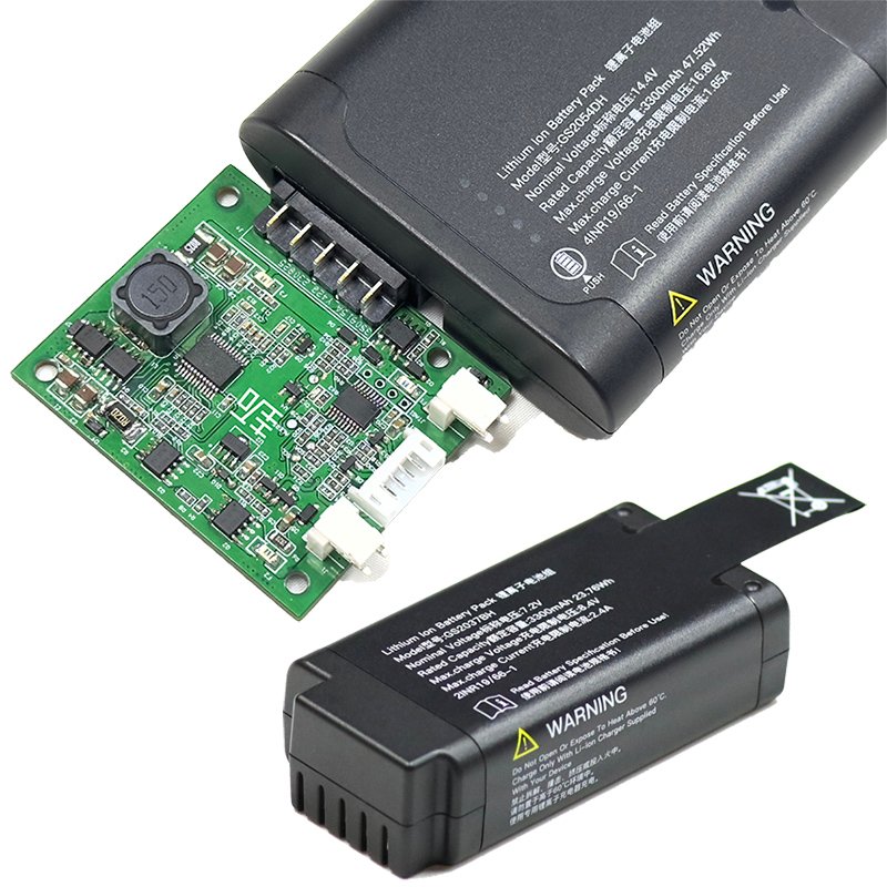
Phase 3: protection trip tests
This is the phase that is most often reduced to a document review, and the phase that most often causes trouble later. The objective is to prove that each protection function actually opens the contactor at the intended threshold and that the system recovers in a defined way.
| Test | How to perform it safely | What to record |
|---|---|---|
| Cell overvoltage trip | Raise the charge voltage reference or use the BMS test mode at low current | Threshold at trip, recovery threshold, time to contactor open |
| Cell undervoltage trip | Discharge at low current into a load bank | Threshold at trip, recovery condition, cell voltages at trip |
| Overcurrent, charge and discharge | Load bank or PCS current limit ramp, staying inside cable ratings | Current at trip, delay time, which device operated first |
| Overtemperature | Sensor substitution or chamber test, per manufacturer’s method | Sensor used, threshold, whether charge and discharge trip separately |
| Communication loss | Disconnect the inter-rack or controller link | Time to safe state, alarm raised, automatic recovery or manual reset |
| Insulation fault detection | Where an insulation monitoring function exists, apply a known test resistance | Detection threshold and alarm path |
| Contactor and precharge sequence | Power-cycle the rack and observe the sequence | Precharge time, inrush behaviour, any repeated attempts |
| Emergency stop | Operate the site E-stop with the rack energised | Devices that opened, time to zero volts at the terminals |
Two rules make this phase credible. Test one function at a time so the cause of a trip is unambiguous, and restore the configuration after each test with a recorded verification. If a protection cannot be tested on site, say so in the handover pack and state what evidence replaces the test, such as factory records or a manufacturer’s type-test report. An untested function that is claimed as tested is worse than a documented gap.
Phase 4: capacity and efficiency evidence
A capacity test at commissioning establishes the baseline against which warranty claims will later be judged. Three decisions define the result, and all three belong in the test procedure.
Where the measurement is taken. Capacity at the DC terminals is not the same as energy delivered at the AC meter. DC capacity is a property of the battery; round-trip efficiency includes the PCS. State which one is being measured, and with which instrument class.
At what rate and temperature. A capacity test at 0.2C and 25 °C will produce a higher number than one at 0.5C and 35 °C. Use the rate and temperature the warranty references; if the site is at 38 °C, record the ambient and note the deviation.
Over what state-of-charge window. Testing from 100% to the BMS cutoff measures usable energy, not nameplate capacity. Both are legitimate; they answer different questions, and mixing them causes disputes.
A practical sequence for a rack: charge to the upper limit with the PCS, rest for a defined period, discharge at the agreed rate to the lower limit while logging pack voltage, current, temperature and cumulative energy, then recharge and confirm that the returned energy is consistent with the expected round-trip efficiency. Logging interval matters; one-minute averages hide the PCS efficiency curve at low load.
Rack-level balancing should also be confirmed here. After a full charge and a rest, cell voltages across the string should sit inside the balancing window stated by the manufacturer. A string that will not converge points to a weak module, a failed sense lead or a balancing configuration error, and all three are easier to resolve before handover.
Phase 5: thermal behaviour and site integration
Thermal verification is not a formality. Capacity, available power and life all depend on cell temperature, and the rack’s thermal design assumes a specific airflow and ambient range.
- Run a continuous charge and discharge cycle at the site’s expected peak load and record module temperatures at the top, middle and bottom of the rack.
- Compare the spread across the rack. A large spread means airflow is short-circuiting or a module position is starved, and the hottest module will age first.
- Confirm that the cooling or HVAC control is interlocked so the rack cannot be charged at full rate with failed ventilation.
- Verify the fire detection interface where the project includes one: the signal path, the device that receives it, and the action it triggers. Test the interface, not just the wiring.
- Check that temperature and humidity sensors are located where they measure rack conditions rather than the room’s coolest corner.
The safety basis for the rack itself comes from the module and system design, not from the commissioning visit. Industrial lithium packs are qualified against standards such as IEC 62619, which covers safety requirements for lithium cells and batteries in industrial applications, and independent test programmes at facilities such as the Sandia Energy Storage Safety laboratory show the kind of abuse and performance data that should sit behind a supplier’s claims. Commissioning confirms the installed system behaves as designed; it cannot create evidence that the design was never tested. When a project owner questions why the test scope is not a formality, the US Department of Energy energy storage programme overview is a neutral reference for how storage systems are characterised and deployed.
The handover pack
A commissioning report that consists of a tick list and a photograph of the rack will not support a warranty discussion. The handover pack should include:
- As-built single-line diagram and rack layout with module serial numbers by position.
- Configuration export from every BMS and controller, with firmware versions and timestamps.
- Torque records and insulation resistance readings by rack.
- Protection trip test results: threshold, measured value, response time, and the person who witnessed it.
- Capacity test data: rate, temperature, start and end voltage, energy in and out, and the instrument used.
- Thermal map at peak load, with ambient conditions.
- Open items with owners and dates, including any protection function not tested on site.
Where the capacity evidence is used to support a performance guarantee, have the test witnessed or the instruments calibrated with traceability that the customer accepts. Certificates issued under the ILAC arrangement are the usual way to demonstrate that a calibration or test report is traceable.
Common findings and how to dispose of them
| Finding | Likely cause | Disposition |
|---|---|---|
| One module reads a much lower cell voltage than its neighbours | Deep discharge in storage, failed sense lead, or a module swapped from another batch | Isolate and test the module individually; replace rather than rebalance if capacity is affected |
| Rack trips on overvoltage before reaching the target charge voltage | One cell or module offset; balancing not converged; charge voltage configured per module instead of per cell | Check cell-level data, run a balancing cycle, verify the configuration against the cell datasheet |
| Capacity below expectation at first test | Test at a higher rate or temperature than the warranty basis; modules not fully balanced; SOC calibration incomplete | Repeat at the contractual conditions before raising a claim |
| Temperature spread across modules above the design assumption | Airflow obstruction, missing blanking panels, rack installed against a wall | Correct the airflow path and repeat the thermal run |
| PCS does not respect current limits from the BMS | Protocol mismatch, wrong register map, or limits disabled in the PCS configuration | Resolve at the communications level; do not accept rack protection as the operating limit |
| Alarm appears at the controller with the wrong description | Alarm mapping table not loaded or offset by one | Correct the mapping and retest each alarm point |
Specifying racks so commissioning is short
Most commissioning problems are created at the quotation stage. A purchase specification that states only “48 V, 100 Ah, LiFePO4” leaves the integrator to discover the rest on site. Four specification items prevent the majority of findings:
- The communication protocol, register map and firmware version that the PCS expects, not just “CAN”.
- Protection thresholds and recovery behaviour, agreed as values with a tolerance rather than “BMS protected”.
- The capacity test basis: rate, temperature, SOC window and measurement point.
- Documentation deliverables: configuration export format, test records and the change notification process.
Our 48 V rack-mount LiFePO4 production page describes the module formats and BMS options used in these systems, and the solar and storage pack assembly page covers larger configurations. If you are specifying a rack for a project, the LiFePO4 pack selection notes for solar storage and the BMS function overview are useful before the RFQ goes out. Send the site conditions and PCS model through the contact page and we will confirm which configuration and documentation set fits.
Frequently asked questions
How long should rack commissioning take?
For a single rack with the PCS already commissioned, the inspection and protection phases typically fit into one working day, and the capacity test adds a charge and discharge cycle at the chosen rate. Multi-rack sites scale roughly linearly for inspection and trip testing, but the capacity test can often be run on a sample of racks if the project specification allows it. The variable is usually site readiness, not battery work.
Can the capacity test be replaced by the factory test report?
No, if the guarantee is to be measured on site. The factory report describes a module under factory conditions; the site test describes the installed system after transport, storage and installation. A reasonable compromise is a full test on one rack plus a shorter verification on the others, provided the project documents that logic in advance.
Who should witness protection trip tests?
Someone with the authority to accept the result on behalf of the asset owner, plus the commissioning engineer who performed the test. Where the project has an independent engineer or insurer with an interest in the battery system, include them in the plan rather than arranging a second visit.
What the record is for
The commissioning record has one job: to make later conversations factual. When a rack underperforms in year three, the baseline capacity, the configured thresholds and the thermal map from the first week decide whether the issue is a warranty matter, an operating condition, or a design limit that was known at handover. Building that record costs a day; reconstructing it costs considerably more.