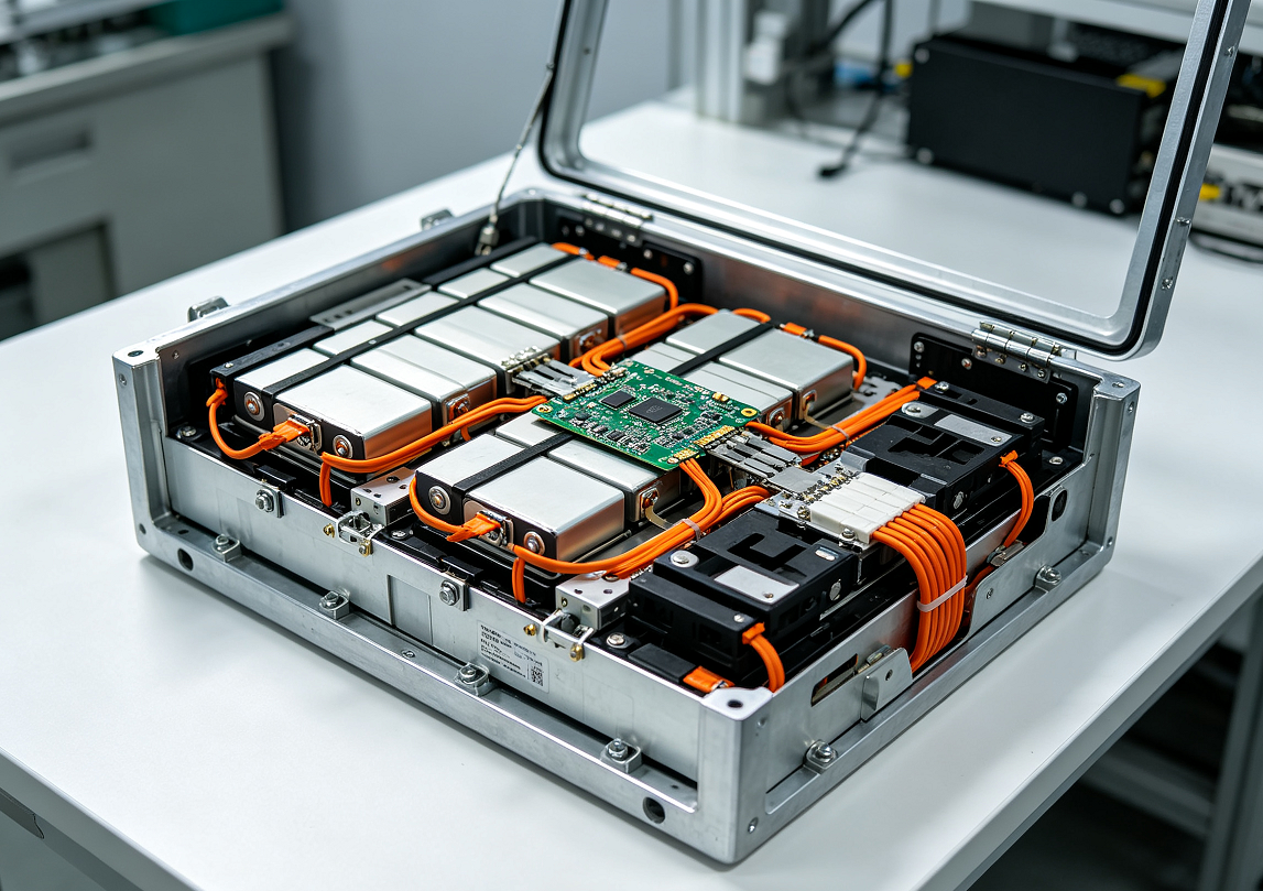
On a custom lithium battery pack, the connectors and wire harness are small items on the bill of materials and a disproportionate source of field problems. A connector labelled “5 A” can carry 5 A comfortably at room temperature in free air with two contacts energised, and run hot or fail early in a sealed housing at summer ambient with eight contacts carrying current in the same body. The label is not wrong; the rating was measured under conditions that the application does not reproduce. This article sets out what a hardware engineer should specify for pack connectors and harnesses — beyond the headline current — so that the assembly survives its real environment rather than its datasheet.
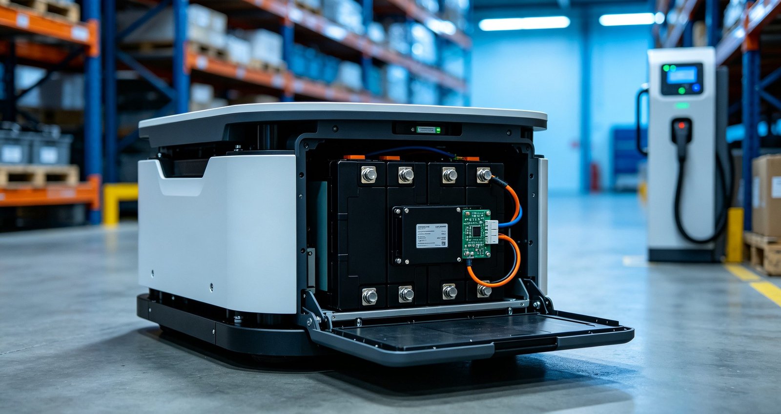
The rated number versus the rating you get
Connector current ratings are established under defined test conditions, and the conditions matter more than the number. Contact temperature rise depends on ambient temperature, on how many contacts in the housing are carrying current at once, on wire size feeding the contact, and on airflow. IEC 61984, the safety standard for connectors, covers connectors with rated voltages above 50 V up to 1000 V AC and DC and rated currents up to 125 A per contact, and notes that for connectors below 50 V it may be used as a guide — which is exactly the situation in most battery packs. The practical consequence for a specification writer: require the rating conditions to be stated, and derate in writing for the conditions the application actually presents.
Derating for the energised-contact count is the effect buyers most often miss. Multiple contacts carrying current in one housing share the heat path, so an eight-pin power connector carrying current on every pin runs warmer per contact than the same connector carrying current on two pins, even though the per-contact rating is unchanged. A housing selected on a bench prototype, where short jumpers and a cool lab hide the difference, can land in a sealed machine at summer ambient with no margin left. The same logic applies to pulse loads: a motor-start pulse that lasts a second is benign, but the same pulse repeated every few seconds accumulates heat like a lower continuous load, so pulse ratings are only meaningful when duration and repetition rate travel with them.
Ingress protection adds a further subtlety. Under the two-numeral system of IEC 60529, what matters for a connector is the rating of the mated pair in its service state, not the rating stamped on the receptacle. Many circular and rectangular connectors are sealed when mated and open-faced when not; a pack that sits half its life with a disconnected power lead is protected for only half its life. Where connectors spend time unmated, specify a protective cap, a parking receptacle or a sealed unmated construction, and say so on the drawing rather than leaving the assembler to guess.
| Parameter | What to specify | Why it is on the list |
|---|---|---|
| Continuous current | Value plus conditions: ambient, contact count energised, wire gauge, airflow | The same connector can be adequate or marginal depending on all four |
| Peak / pulse current | Amplitude, duration, repetition rate, number of pulses | Motor start and inrush loads heat contacts in ways a continuous rating does not describe |
| Voltage and creepage | Working voltage, pollution degree, any safety requirement on the finished device | Clearance and creepage set the separation between contacts, not just the material rating |
| Contact resistance | Initial limit and end-of-life limit, measured per contact | Rising contact resistance is the mechanism behind most connector heating failures |
| Mating cycles | Expected service events, not just the datasheet maximum | A pack that is swapped three times a day wears connectors far faster than one wired permanently |
| Retention and vibration | Locking mechanism class, retention force, vibration test at assembly level | Unmated or fretting contacts under vibration are a common mobile-equipment failure |
| Ingress protection | IP rating of the mated pair, not the unmated receptacle | Many connectors are sealed mated and open-faced unmated; the service state matters |
| Temperature rating | Insulation rating of wire and housing, with the pack’s worst ambient stated | Insulation ages near hot surfaces even when the conductor itself is fine |
Three interconnect systems, three different jobs
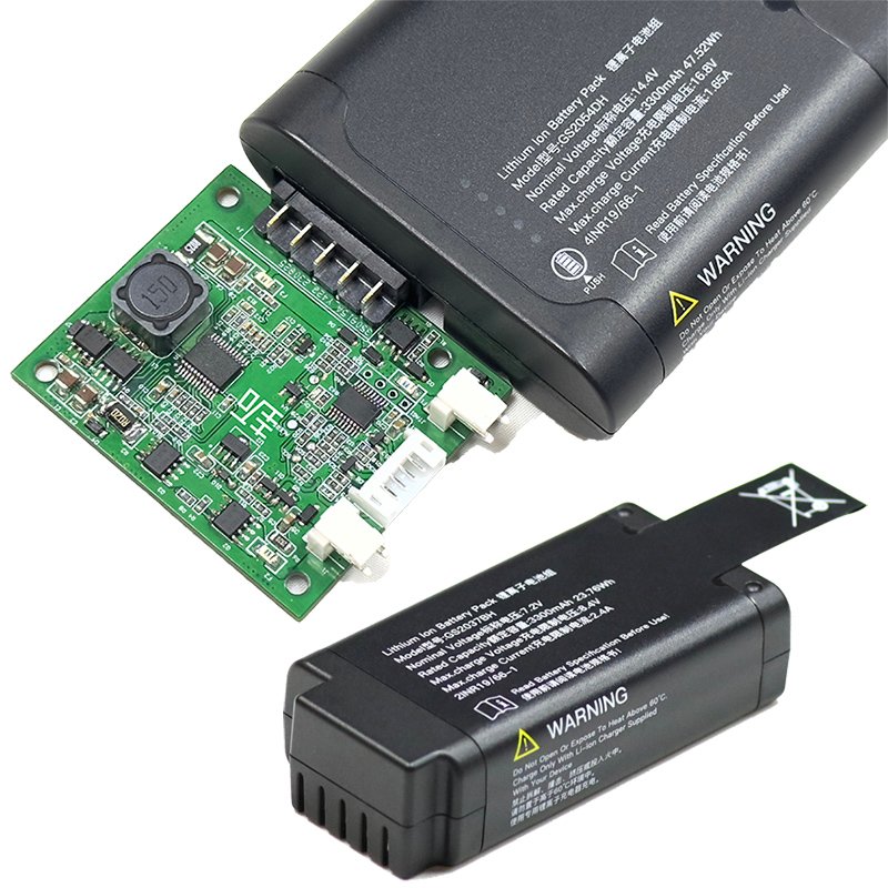
A pack is not one connector problem but three, and they fail differently. The main power connector carries charge and discharge current between pack and device. The balance or monitor connector taps individual cell groups for the BMS. The communication connector carries data — fuel gauge, CAN or RS485, enable lines. Mixing their requirements up is one of the most common specification errors.
| System | Typical duty | Key specification points | Common mistakes |
|---|---|---|---|
| Main power | Full charge and discharge current | Derated continuous rating, locking mechanism, mated-pair IP, contact resistance limit | Rating taken from the label without derating; relying on friction fit in a vibrating machine |
| Balance / monitor | Milliamps per cell group | Pin count matches series count, insulation between adjacent pins, keyed to prevent mis-mating | Using an unkeyed header where an off-by-one mis-mate can short adjacent cell groups |
| Communication / signal | Data and enable lines | Shielding where motors or inverters are near, ESD protection, correct latch type | Running unshielded signal harness parallel to power harness in noisy equipment |
Two rules are worth writing into the specification explicitly. First, the balance connector must be keyed so that it physically cannot be inserted one pin off; a mis-mated balance connector connects two cell groups at different potentials through a thin contact. Second, the main power connector must not be the only mechanical retention between pack and device in anything that moves — a latch or screw lock belongs in mobile and robotics applications, where the robotics pack design notes discuss the wider mounting and vibration context.
Contact plating and base materials deserve one sentence in the specification too. Plating thickness and underplating set how contact resistance behaves over thousands of mating cycles and years of humidity, and the cheapest contact finish on the shelf is rarely the one that holds its resistance limit to end of life. Where the service environment is humid or chemically active — washdown areas, coastal installations, cold-chain equipment — state that environment in the RFQ and let the supplier propose a finish rated for it, then hold the contact-resistance limit from the table above at incoming inspection and at any periodic re-check.
Harness decisions that quietly decide reliability
Wire gauge gets all the attention, but the harness details around it do more long-term damage control. Conductor size sets resistance and heating, and it should be chosen for the pack’s true duty cycle rather than a single worst-case peak; the relationship between length, gauge and voltage drop is straightforward arithmetic that belongs in the pack design review, not the assembler’s judgement call.
The quieter items matter just as much:
Stranding and flexibility. Fine-stranded, high-flexibility conductors survive movement; solid or coarse-stranded wire work-hardens and fractures where it exits a crimp. For packs in machines that articulate, flexibility at the harness is a specified property, not a purchase-detail.
Insulation temperature rating. Wire routed near cells, busbars or heat-generating electronics needs an insulation class matched to that environment, and bundles should be routed away from the hottest surfaces or protected by sleeving.
Crimp quality. A crimp is a controlled deformation process, not a squeeze. Tooling matched to the contact, wire stripped to length, and pull-force sampling on the production line are what make a crimp repeatable; the NIST/SEMATECH handbook chapter on sampling and acceptance control is the standard reference for sizing such checks. Solder-filled crimps fill a gap in cheap tooling but make the joint stiff right where flexing happens, which is why high-vibration harnesses avoid them.
Strain relief and service loops. Every harness should be able to move slightly without loading a connector’s solder joints, and every bundle should be secured at intervals so vibration does not work a single clamp loose.
Failure modes and the design response
| Field failure mode | Root mechanism | Design countermeasure |
|---|---|---|
| Connector housing melts or discolours at one contact | Contact resistance grew (oxidation, lost spring force) and the contact carried current outside its conditions | Derating with stated conditions; contact resistance limits with periodic re-check |
| Intermittent operation under vibration | Micro-motion between contact surfaces (fretting) or partial un-mating | Positive latch, retention force specified, harness strain relief, assembly-level vibration test |
| BMS reads wrong cell voltages | Balance connector mis-mated, or a balance pin contact corroded | Keyed, polarised balance connector; conformal protection in humid environments |
| Corrosion at outdoor connectors | Sealing assumed on the receptacle but the service state is unmated, or condensation cycles | Mated-pair IP rating specified; cap or parking position for unmated connectors |
| Wire fracture at the crimp barrel | Work hardening at a stiff joint, often aggravated by solder fill and short service loops | High-flex strand, proper crimp tooling, service loops, secure the bundle |
| Insulation damage against a housing edge | Harness routed against a sharp or hot surface with no protection | Routing defined on the drawing, sleeving or grommets at pass-throughs |
None of these are exotic. They are the ordinary failure modes of current-carrying interconnects, and each has a documented design response. What turns them into field returns is usually a specification that stopped at “connector: XT60, wire: 12 AWG” and left the rest to assembly.
What to ask the pack supplier
Four questions separate a supplier who treats interconnect as an engineering subject from one who treats it as procurement. Ask which connector series is proposed and what its rating conditions are; how the harness is crimped and sampled in production; what vibration and mating-cycle testing is done at assembly level; and how connector choice interacts with the pack’s IP rating and the finished device’s safety file. The BMS functions that ride on these connections — protection thresholds, fuel gauge accuracy, communication protocols — are described in the BMS overview, and the smart pack with BMS page shows how those functions are packaged into a product. For the structural questions around the harness — cell layout, current paths, thermal paths — the RFQ checklist lists the inputs worth sending with your first enquiry, and our engineers can review a proposed interconnect scheme through the contact page.
Interconnect is one of the few areas of pack design where a modest amount of specification discipline pays back quickly: the parts are inexpensive, the failure modes are well understood, and the difference between a label and a derated rating is exactly the difference between a pack that passes qualification and one that comes back under warranty.