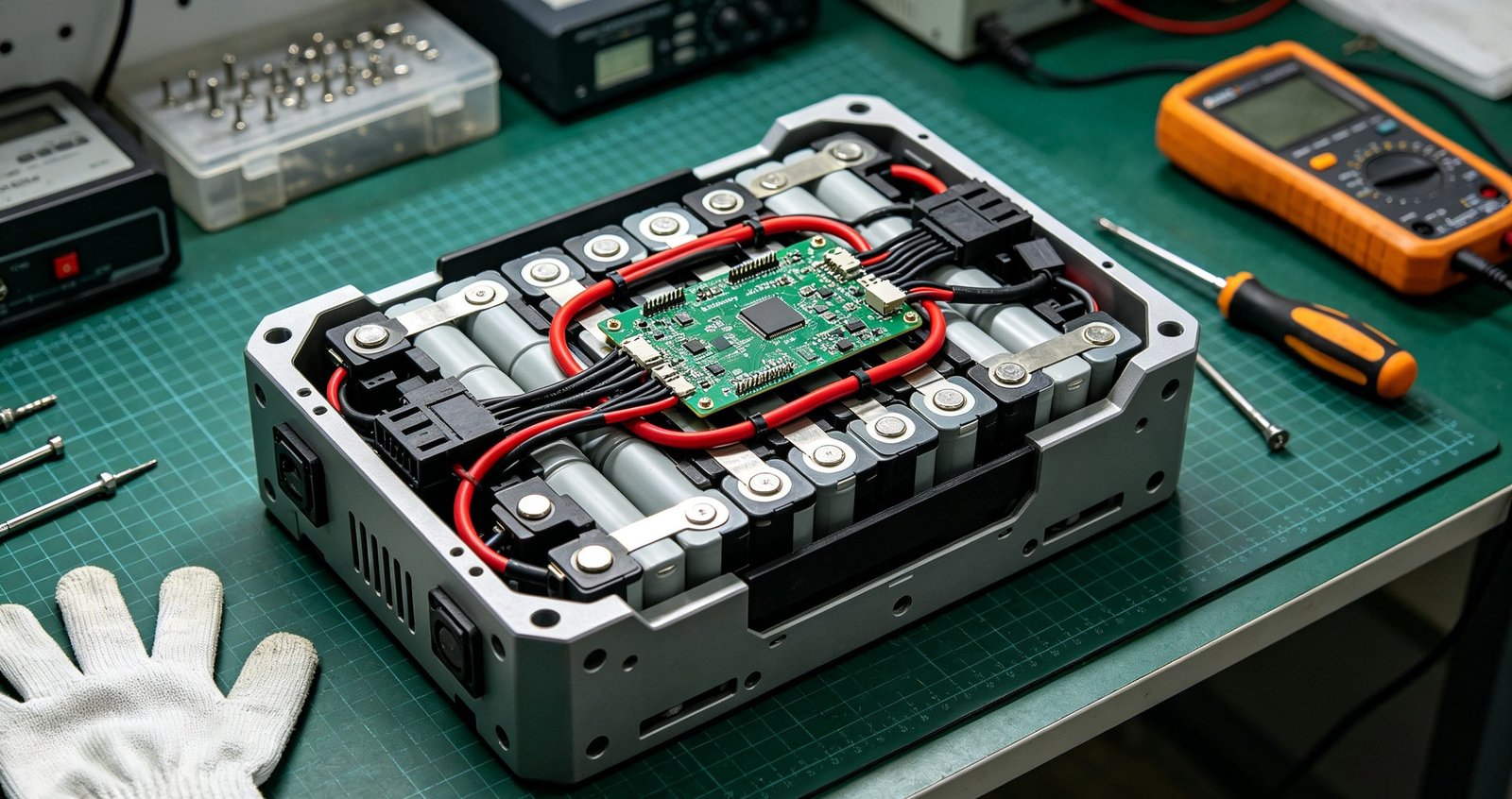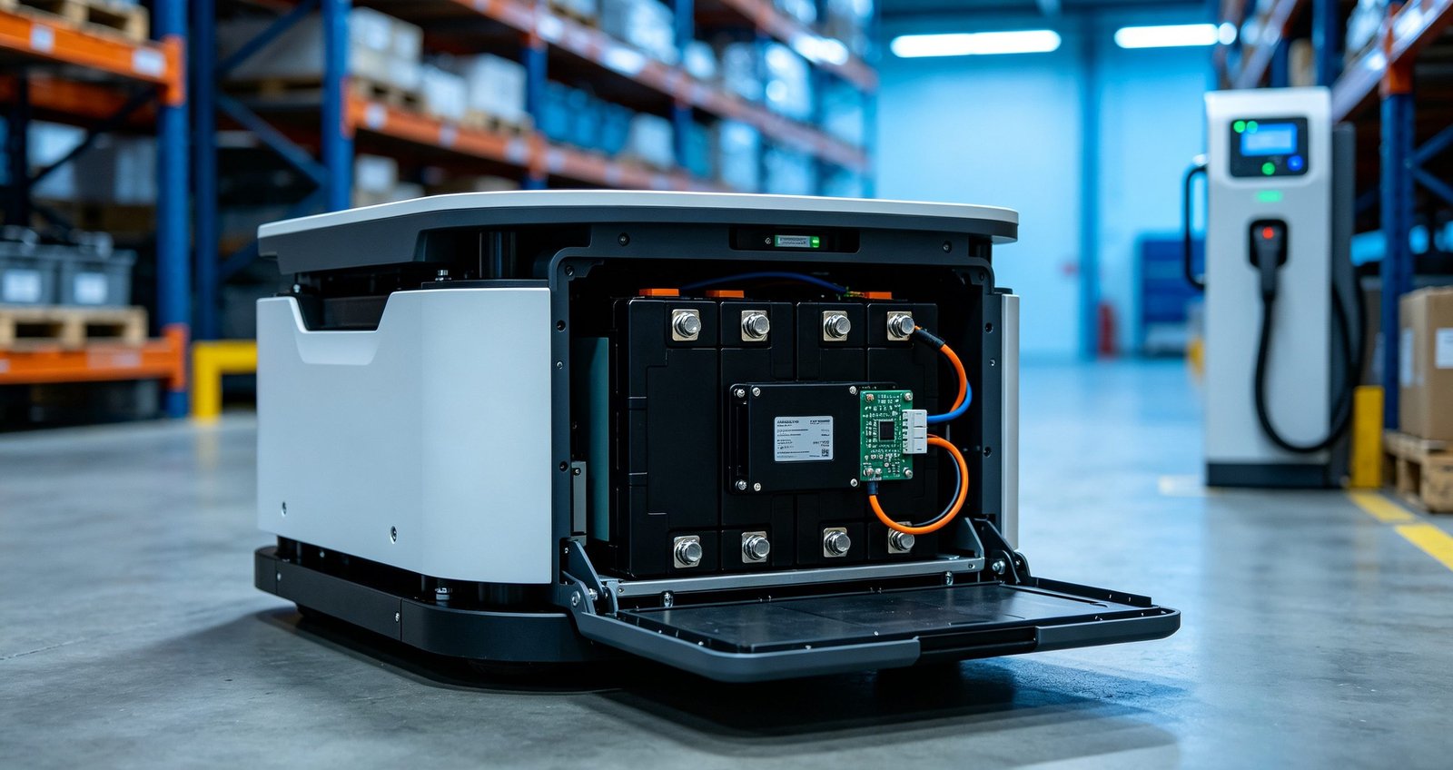
For a multi-shift AGV or AMR fleet, the charging strategy is a fleet-design decision made before the first robot is ordered: it fixes fleet size, battery chemistry, pack sizing, charger infrastructure and even the electrical service to the building. The short answer for most 24/7 intralogistics fleets: opportunity charging of lithium packs in a partial state-of-charge window, placed at natural dwell points in the mission profile, with battery swap reserved for duty cycles that leave no usable dwell time or applications where a stopped vehicle is unacceptable. This article compares the two strategies on the parameters that actually decide the outcome and sets out the battery-side specification an OEM or integrator needs to write either one into an RFQ.
What each strategy actually means
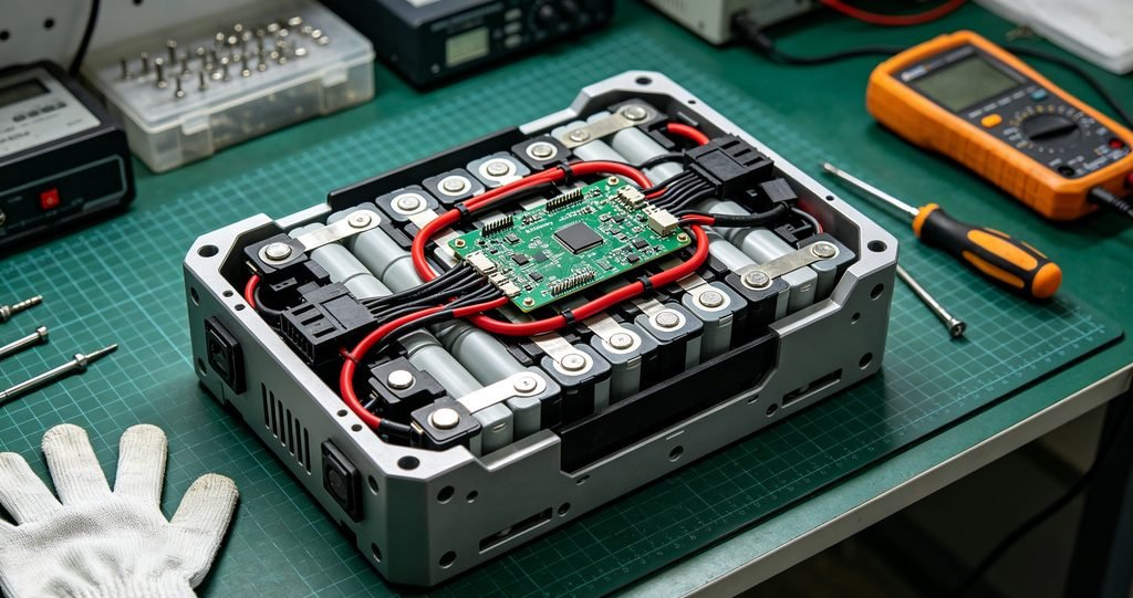
Battery swap standardizes the pack, adds swap infrastructure — manual exchange bays or automated swap stations — and carries a spare-pack inventory, so a depleted vehicle swaps in minutes and the depleted pack recharges off-vehicle. Opportunity charging puts chargers where vehicles already stop: pick faces, drop-off buffers, elevator queues, staging lanes. The vehicle tops up in short sessions during normal operation and rarely parks specifically to charge. A third pattern, full-shift charging, exists mainly in single-shift sites where vehicles can sit overnight; it is the legacy lead-acid model, and treating it as the default is what makes fleets oversized.
The decision variables
Four variables decide the strategy, and three of them come from route data rather than opinion. First, dwell profile: how long vehicles stop, where, and whether those stops are long enough to recover meaningful energy. Second, duty energy: the energy a vehicle consumes per hour of real mission work, including lifts and accelerations, not just average drive current. Third, fleet availability target: the percentage of vehicles that must be mission-capable at any moment, which determines whether a 20-minute charge stop is a rounding error or an incident. Fourth, infrastructure budget and site electrical capacity, because a fleet of dock chargers is a load-management problem for the building, not a set of independent appliances.
Swap versus opportunity charging, parameter by parameter
| Criterion | Battery swap | Opportunity charging |
|---|---|---|
| Fleet availability | Highest for the vehicle — swap takes minutes | High when chargers sit at natural dwell points; degrades if charger placement is wrong |
| Pack design | Must be standardized and tool-swappable; connector cycle life becomes a design driver | Fixed or semi-fixed pack; docking contactors or contactless pads |
| Infrastructure | Swap station or exchange bay plus spare-pack chargers and inventory | Distributed dock chargers at dwell nodes; lower civil works |
| Electrical load profile | Concentrated at swap station; off-vehicle charging is schedulable | Distributed and stochastic; needs concurrency management as fleet grows |
| Battery degradation drivers | Deep cycles if packs run full-shift between swaps | Many shallow cycles; stress depends on charge rate, temperature and SOC window |
| Operational labor | Manual swap needs staff; automated swap needs capital | Minimal once placement is correct |
| Best fit | Extreme duty cycles, no dwell time, or uptime-critical single vehicles | Most 24/7 warehouse and factory fleets with predictable dwell points |
One planning note that gets missed: charger congestion behaves like queueing, not like inventory. Two chargers at the busiest pick face will outperform four chargers in a corner nobody routes through, because the second layout adds deadhead travel to every charging event. Treat charger count and placement as an output of the route simulation, then re-check it after go-live when real dwell data replaces assumptions.
How the strategy interacts with battery chemistry
Charging strategy and chemistry cannot be chosen independently, because the chemistry sets what the pack tolerates per charging event.
| Chemistry | Behavior under frequent partial charging | Where it fits in an AGV fleet |
|---|---|---|
| LFP (LiFePO4) | Tolerates shallow cycling well; comparatively stable thermal behavior; lower energy density than NMC | Multi-shift fleets with daily partial cycling — the default for opportunity charging |
| NMC / NCA | Higher energy density; degradation more sensitive to high SOC dwell and charge rate | Weight- or space-limited vehicles with moderate cycle counts |
| LTO | Accepts very high charge rates and extreme cycle counts; low nominal voltage and low energy density | Duty cycles needing multi-C charging in minutes, often with swap |
These are directional properties, not guarantees: the degradation rate of any specific cell depends on temperature, state-of-charge window, charge rate and cycling pattern acting together, which is exactly how long-duration battery research programs characterize cells — Sandia National Laboratories’ energy storage systems laboratory publishes the methodology behind that kind of testing. What the direction does tell you is that the “swap means deep cycles, opportunity means shallow cycles” rule of thumb pushes most multi-shift sites toward LFP under opportunity charging, while energy-density-critical AMRs may accept NMC with tighter SOC management.
Two constraints that override strategy choice
Whatever the fleet-level economics say, two electrochemical constraints bound the design. First, charging temperature: lithium-ion cells generally cannot be charged below 0 °C without lithium plating, and cell datasheets typically restrict charging to 0 °C to 45 °C — narrower than the discharge window. Fleets running in cold storage or loading docks in winter need packs with cell heating before charge, which is a pack-level requirement, not a charger setting. Our cold-weather LiFePO4 pack design note covers what that heating layer changes. Second, charge rate: high charge current at low temperature or high SOC accelerates degradation and, at the extreme, becomes a safety variable. The opportunity-charging pattern is only gentle if the charger is not fighting the duty cycle — short windows blasted at maximum current trade uptime today for tighter thermal margins and faster capacity fade later.
Writing the battery-side specification
Whether the fleet charges by swap or by dock, the battery RFQ should carry the charging strategy as explicit pack requirements. The specification format matters more than the numbers below, which are illustrative for a mid-size AMR pack:
| Parameter | Specification format (example) | Why it belongs in the RFQ |
|---|---|---|
| Charge current limits | Standard 0.5C continuous; 1C permitted +15 °C to +45 °C, SOC 10–80% | Sets whether a dwell window recovers useful energy |
| Charge temperature window | 0 °C to +45 °C with cell heating below +5 °C | Cold-storage and dock fleets fail here first |
| SOC operating window | Normal operation 20–90% SOC | Defines usable capacity and degradation management |
| Charger communication | CAN 2.0B handshake; charger reads BMS charge-current limit in real time | Prevents charger-versus-BMS conflicts |
| Dock cycle life | ≥ 10,000 docking cycles on charge contacts | Contact wear dominates swap and dock maintenance |
| Charge time target | 0–80% SOC in ≤ 45 min at +25 °C | Anchors fleet simulation assumptions |
A smart pack with an integrated BMS that exposes charge-current limits and state-of-charge data over CAN makes both strategies safer, because the charger obeys the pack rather than a fixed profile. For swap-based fleets, add the pack-to-vehicle interface: guided mechanical registration, contact protection against hot-plug arcing, and a connector rated for the swap cycle count. The robotics battery pack designs we build for AGV and AMR OEMs carry these interface requirements as standard line items, and the full range of formats is on the products page.
Safety and compliance context
Charging strategy also has a compliance dimension. Machine-level safety for driverless industrial trucks is governed by ISO 3691-4, whose scope explicitly excludes requirements for power sources — meaning the battery and charging system are qualified against battery standards, not the truck standard. For industrial lithium packs, that standard is IEC 62619:2022, which covers lithium cells and batteries for industrial applications and names automated guided vehicles in its scope, including evaluation of the battery and BMS combination; the current edition is available from the IEC webstore, and its national adoptions such as DIN EN ISO 3691-4:2023 are documented alongside it in standards catalogues. Smaller AMR packs that qualify as portable applications may instead fall under IEC 62133-2, which changes the report set your RFQ should request. Shipping is a separate track: every pack, swap spare included, needs UN 38.3 documentation before it moves as cargo.
Fleet-level effects worth simulating before purchase
Three second-order effects decide whether the chosen strategy survives contact with operations. Charger concurrency: simultaneous charging sessions can set a building demand peak that outlasts the event on the utility bill, so group chargers and stagger sessions as the fleet grows. Battery aging diversity: packs on the hardest routes age fastest, so route rotation extends fleet battery life at zero capital cost. Data visibility: a BMS that logs SOC, temperature and cycle history per pack turns battery replacement from calendar-driven to condition-driven, which is the difference between planning a swap-in and reacting to a dead vehicle.
Frequently asked questions
Can an existing NMC fleet move to opportunity charging?
Usually yes, with a narrower SOC window and a lower charge-current ceiling than an LFP fleet would use, because NMC tolerates high-SOC dwell less well. The realistic first step is limiting the charge target — for example capping opportunity sessions at 80% SOC — and watching capacity trends per pack before changing hardware.
Do wireless charging pads change the trade-off?
They remove the docking-accuracy problem and contact wear, at the cost of efficiency losses and higher infrastructure price per position. The strategy question — swap versus opportunity — stays the same; only the dock mechanism changes.
How many chargers does a fleet need?
No universal number exists: it falls out of the dwell simulation — count the dwell events per hour that exceed a useful charge duration, then add headroom for the busiest hour. Sites that fix charger count before running the simulation usually buy chargers for the routes they planned, not the routes the fleet actually flies.
Bottom line
Choose from route data: map dwell points and duty energy first, size the pack and SOC window second, then let swap-versus-opportunity fall out of the availability target. Specify the battery side explicitly — charge-current limits with conditions, charge temperature window, SOC window, charger communication and dock cycle life — because that specification is what makes quotes comparable and fleets reliable. If you are defining an AGV or AMR power system, send the duty profile and fleet targets through our contact page; we respond with a charging-strategy proposal and a pack specification you can put directly into an RFQ.